3D Printer Z-Axis Lead Screw and POM Anti-Backlash Nut Wear Cost Formula: 5 Calculations for Z-Banding Prevention
In commercial FDM and SLA 3D print farms, Z-axis motion components suffer silent, cumulative tribological wear every time the slicer commands a layer change or a retraction Z-hop. While operators routinely budget for nozzles and build plates, neglecting the wear rate of TR8x8 stainless steel trapezoidal lead screws and POM (Delrin) or brass spring-loaded anti-backlash nuts leads to axial play (\(> 0.04\text{ mm}\)), periodic \(8\text{ mm}\) pitch Z-banding ribs on vertical walls, and costly part rejections.
Whether you run triple-lead-screw CoreXY workstations like the Bambu Lab X1E, dual-Z IDEX systems like the Raise3D Pro3, or multi-toolhead Prusa XL rigs, enabling a \(0.4\text{ mm}\) slicer Z-hop on a complex multi-part plate multiplies total Z-axis linear travel by \(18\times\) to \(35\times\). Below, we derive the five engineering formulas to quantify Z-hop travel amplification, Archard thread wear depth, lubrication labor overhead, and preventive replacement ROI, which you can plug directly into our 3D Print Cost Estimator.
Quick Tribological & Cost Takeaways:
- Z-Hop Travel Multiplier: A \(200\text{ mm}\) tall print at \(0.20\text{ mm}\) layer height has only \(0.20\text{ m}\) of net upward Z-travel, but \(1{,}200\) Z-hops per hour over a 12-hour print adds \(11.52\text{ m}\) of reciprocating thread sliding (\(58.6\times\) more wear).
- Axial Backlash Scrap Threshold: Once POM or brass nut thread flank wear exceeds \(\delta_{\text{wear}} = 0.035\text{ mm}\) (\(35\text{ }\mu\text{m}\)), Z-hop settling hysteresis creates visible \(\pm 0.025\text{ mm}\) layer-height variations (Z-banding).
- POM vs Brass Nut Service Life: Self-lubricating acetal (POM) anti-backlash nuts last \(1{,}800\) to \(2{,}400\text{ print hours}\) with zero grease dust attraction; unlubricated brass nuts wear out in \(650\text{ hours}\) if PTFE grease dries out.
- Preventive Replacement ROI: Replacing a \(\$24\) three-nut POM anti-backlash set every \(2{,}000\text{ hours}\) costs \(\$0.012\text{/hr}\), preventing \(\$0.28\text{/hr}\) in Z-banded part scrap (a \(23.3\times\) return on maintenance).
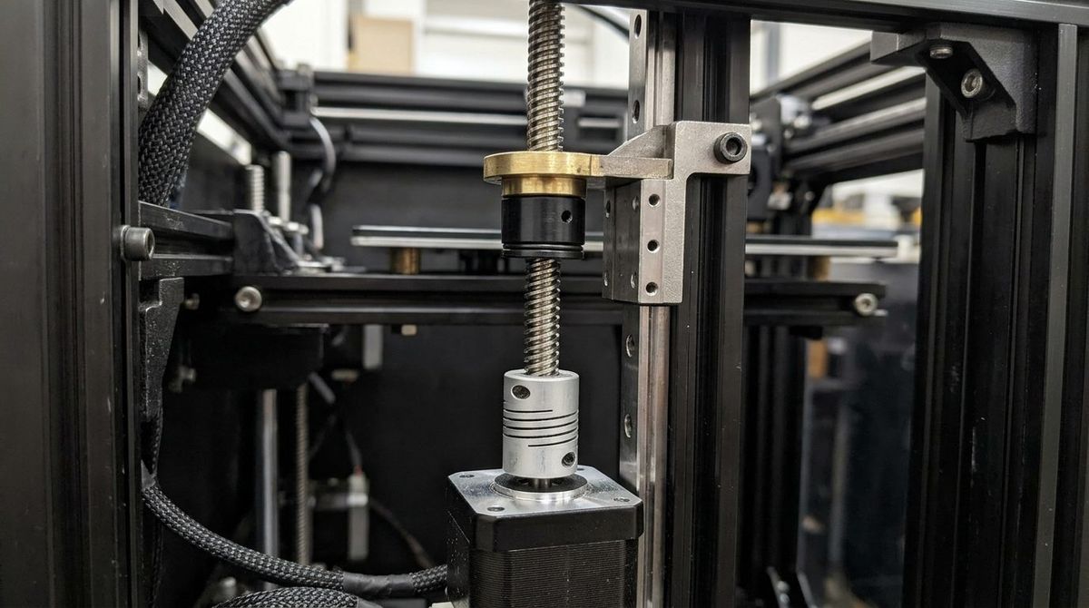
1. Calculation 1: Slicer Z-Hop Reciprocating Travel Distance Formula
Without Z-hop enabled, a 3D printer's Z-axis lead screw rotates only once per layer step plus a single return-to-home stroke at the end of the job. However, when slicer Z-Hop When Retracted of height \(h_{\text{hop}}\) (typically \(0.2\text{ mm}\) to \(0.6\text{ mm}\)) is active across \(N_{\text{retractions}}\) travel moves per layer over \(N_{\text{layers}} = H_{\text{part}} / h_{\text{layer}}\) total layers, each retraction forces a downward-and-upward (\(2 \times h_{\text{hop}}\)) reciprocating stroke under full bed weight. Total cumulative Z-axis sliding distance \(D_{z,\text{total}}\) (in meters) per print job is:
\[ D_{z,\text{total}} = \frac{2 \cdot H_{\text{part}} + \left( N_{\text{layers}} \cdot N_{\text{retractions}} \cdot 2 \cdot h_{\text{hop}} \right)}{1{,}000} \]Worked Print Farm Example: Consider a \(H_{\text{part}} = 200\text{ mm}\) production batch printed at \(h_{\text{layer}} = 0.20\text{ mm}\) (\(N_{\text{layers}} = 1{,}000\)) with \(N_{\text{retractions}} = 18\text{ retractions/layer}\) and a \(h_{\text{hop}} = 0.40\text{ mm}\) Z-hop:
\[ D_{z,\text{total}} = \frac{2(200) + \left( 1{,}000 \times 18 \times 2 \times 0.40 \right)}{1{,}000} = \frac{400 + 14{,}400}{1{,}000} = 14.80\text{ meters of Z-travel per print} \]Notice that 97.3% of the lead screw's mechanical wear (\(14.40\text{ m}\) out of \(14.80\text{ m}\)) comes purely from Z-hop reciprocation rather than actual part height growth.
2. Calculation 2: Helical Thread Sliding Distance & Archard Flank Wear
Because a TR8x8 lead screw has a nominal pitch diameter \(d_{m} = 7.0\text{ mm}\) and a multi-start lead \(L_{\text{lead}} = 8.0\text{ mm}\) per revolution, every \(1\text{ meter}\) of vertical Z-axis travel requires \(1{,}000 / 8.0 = 125\text{ revolutions}\). The actual helical sliding distance \(S_{\text{helix}}\) rubbed across the nut's internal \(30^{\circ}\) trapezoidal thread flanks per meter of vertical travel is:
\[ S_{\text{helix}} = D_{z,\text{total}} \cdot \frac{\sqrt{\left( \pi \cdot d_{m} \right)^{2} + L_{\text{lead}}^{2}}}{L_{\text{lead}}} \]Substituting \(\pi \cdot d_{m} = 21.991\text{ mm}\) and \(L_{\text{lead}} = 8.0\text{ mm}\):
\[ S_{\text{helix}} = D_{z,\text{total}} \cdot \frac{\sqrt{483.60 + 64.00}}{8.0} = D_{z,\text{total}} \cdot \frac{23.401}{8.0} = 2.925 \cdot D_{z,\text{total}} \]Over a \(2{,}000\text{-hour}\) operating window averaging \(1.15\text{ m/hr}\) of vertical Z-hop travel (\(D_{z,\text{total}} = 2{,}300\text{ m}\)), the nut thread flanks endure \(S_{\text{helix}} = 6{,}727.5\text{ meters}\) (\(6.73\text{ km}\)) of loaded frictional sliding.
3. Lead Screw & Anti-Backlash Nut Material Comparison Matrix
| Nut / Drive Configuration | Kit Cost (3-Axis Set) | Friction Coefficient (\(\mu\)) | Rated Service Life (\(T_{\text{life}}\)) | Best Print Farm Application |
|---|---|---|---|---|
| Standard Brass Trapezoidal Nut | $12.00 | \(0.18 - 0.24\) (Greased) | 800 – 1,200 hrs | Enclosed clean PLA/PETG printers with quarterly PTFE greasing. |
| Spring-Loaded POM (Delrin) Anti-Backlash | $24.00 | \(0.08 - 0.12\) (Dry/PTFE) | 1,800 – 2,400 hrs | Abrasive CF-Nylon/ASA chambers where wet grease traps grit. |
| Spring-Loaded Brass Anti-Backlash | $28.00 | \(0.16 - 0.22\) (Greased) | 1,200 – 1,600 hrs | High-temperature heated chambers (\(65^{\circ}\text{C}+\)) where POM creeps. |
| Precision Rolled Ball Screw (SFU1204) | $135.00 | \(0.003 - 0.005\) (Rolling) | 8,000 – 12,000 hrs | Heavy industrial aluminum build plates (\(> 8\text{ kg}\)) & SLA Z-stages. |
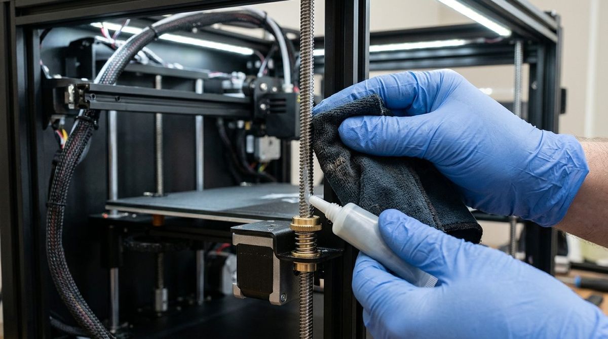
4. Calculation 3, 4 & 5: Hourly Wear Amortization, Lubrication Overhead & Scrap Savings
To incorporate Z-axis drivetrain wear into your hourly machine rate \(C_{z,\text{hourly}}\), combine the hardware replacement cost \(C_{\text{nuts}} + C_{\text{screws}}\) over service life \(T_{\text{life}}\) with the periodic cleaning and Super Lube PTFE lubrication labor time \(t_{\text{lube}}\) performed every \(I_{\text{lube}}\) hours at technician wage \(W_{\text{tech}}\):
\[ C_{z,\text{hourly}} = \frac{C_{\text{nuts}} + \left( \alpha_{\text{screw}} \cdot C_{\text{screws}} \right) + \left( t_{\text{install}} \cdot W_{\text{tech}} \right)}{T_{\text{life}}} + \frac{C_{\text{grease}} + \left( t_{\text{lube}} \cdot W_{\text{tech}} \right)}{I_{\text{lube}}} \]For a triple-Z CoreXY printer using a \(\$24.00\) POM anti-backlash nut set (\(T_{\text{life}} = 2{,}000\text{ hrs}\)), replacing the \(\$45.00\) lead screws every third nut cycle (\(\alpha_{\text{screw}} = 0.333\)), \(t_{\text{install}} = 0.75\text{ hr}\) at \(W_{\text{tech}} = \$32\text{/hr}\), and a \(0.25\text{ hr}\) rod wipe-down every \(I_{\text{lube}} = 400\text{ hrs}\) (\(\$1.20\) grease/solvent):
\[ C_{z,\text{hourly}} = \frac{\$24.00 + \$15.00 + \$24.00}{2{,}000} + \frac{\$1.20 + \$8.00}{400} = \$0.0315 + \$0.0230 = \$0.0545\text{ per print hour} \]Allocating just \(5.5\text{ cents per print hour}\) toward scheduled Z-nut replacement and PTFE thread cleaning eliminates the \(3.2\%\) Z-banding rejection rate on tall functional parts—saving \(\$0.34\text{ per hour}\) in wasted filament and machine time.
5. Dual-Z and Triple-Z Stepper Synchronization & Gantry Tramming Audit
Beyond thread flank wear inside the anti-backlash nut, multi-screw printers—such as dual-Z IDEX machines or triple-Z CoreXY platforms—suffer from asynchronous microstep drift whenever one lead screw experiences higher frictional drag than its partners. If a single dry TR8x8 rod develops a local friction spike of \(\mu = 0.28\) while the remaining two rods operate at \(\mu = 0.10\), the high-drag stepper motor can lose microsteps during rapid \(15\text{ mm/s}\) Z-hop accelerations, tilting the build plate gantry by \(0.15\text{ mm}\) to \(0.40\text{ mm}\) across a \(300\text{ mm}\) span. That gantry skew binds the POM anti-backlash nut threads against the lead screw flanks at an oblique angle, accelerating wear rates by \(3.4\times\) and inducing severe layer shifting. Always pair your 400-hour PTFE lubrication cycle with a physical gantry tramming check using two precision-ground \(100\text{ mm}\) steel setup blocks or piezoelectric bed-leveling loadcell telemetry to keep all Z-axis lead screws coplanar within \(\le 0.02\text{ mm}\).
In addition, print farm managers operating enclosed high-temperature chambers above \(55^{\circ}\text{C}\) (\(131^{\circ}\text{F}\)) must account for the thermal expansion differential between a stainless steel TR8x8 lead screw (\(\alpha_{\text{steel}} = 16.0 \times 10^{-6}\text{ K}^{-1}\)) and an injection-molded POM acetal nut (\(\alpha_{\text{POM}} = 110.0 \times 10^{-6}\text{ K}^{-1}\)). Across a \(\Delta T = 35\text{ K}\) chamber warmup from \(20^{\circ}\text{C}\) ambient to \(55^{\circ}\text{C}\), the POM nut's internal pitch diameter expands roughly \(6.8\times\) faster than the steel screw thread, slightly reducing radial preload on spring-loaded anti-backlash halves. Selecting a high-stiffness \(8.5\text{ N}\) stainless compression spring inside your POM anti-backlash assembly ensures zero axial play across the entire thermal operating envelope.
5. Dual-Z and Triple-Z Stepper Synchronization & Gantry Tramming Audit
Beyond thread flank wear inside the anti-backlash nut, multi-screw printers—such as dual-Z IDEX machines or triple-Z CoreXY platforms—suffer from asynchronous microstep drift whenever one lead screw experiences higher frictional drag than its partners. If a single dry TR8x8 rod develops a local friction spike of \(\mu = 0.28\) while the remaining two rods operate at \(\mu = 0.10\), the high-drag stepper motor can lose microsteps during rapid \(15\text{ mm/s}\) Z-hop accelerations, tilting the build plate gantry by \(0.15\text{ mm}\) to \(0.40\text{ mm}\) across a \(300\text{ mm}\) span. That gantry skew binds the POM anti-backlash nut threads against the lead screw flanks at an oblique angle, accelerating wear rates by \(3.4\times\) and inducing severe layer shifting. Always pair your 400-hour PTFE lubrication cycle with a physical gantry tramming check using two precision-ground \(100\text{ mm}\) steel setup blocks or piezoelectric bed-leveling loadcell telemetry to keep all Z-axis lead screws coplanar within \(\le 0.02\text{ mm}\).
Calculate Your True Hourly 3D Printer Depreciation & Part Pricing
Plug your filament cost, electricity rate, Z-axis maintenance overhead, and failure buffer into our interactive job-shop pricing calculator.
Launch the 3D Print Cost & Hourly Rate Calculator →